Coil Wiring (Pin 1 nearest locking tab)
Coil Pin
| Function
| Haltech Connection
|
1
| ECU Signal
| Ignition Output (Yellow/xxxx)
|
2
| Ground to Cylinder Head
| ---
|
3
| 12V+ Ignition Switched
| ---
|
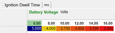
Dwell
DBW Throttle System
This engine uses a single Drive By Wire throttle body.
DBW Throttle Wiring
Position Sensors
Pin
| Description
| Haltech Connection
|
3
| Signal Ground
| Signal Ground (Black/White)
|
4
| TPS2
| AVI 3 (Orange/Red)
|
5
| 5V+
| 5V+ (Orange)
|
6
| TPS1
| AVI 2 (Orange/Black)
|
Drive Motor
Pin
| Haltech Connection
|
1
| DBW 2 (Brown/Red)
|
2
| DBW 1 (Brown/Black)
|
DBW Accelerator Pedal Position Sensors Connection
Pin
| Description
| Haltech Connection
|
1
| 5V+
| 5V+ (Orange)
|
2
| Signal Ground
| Signal Ground (Black/White)
|
3
| Sub Sensor (APP 2)
| AVI 5 (Orange/Green)
|
4
| 5V+
| 5V+ (Orange)
|
5
| Signal Ground
| Signal Ground (Black/White)
|
6
| Main Sensor (APP 1)
| AVI 4 (Orange/Yellow)
|
MAP Sensor
This vehicle comes with a MAP sensor located on the throttle body. The sensor is only used by the OEM ECU for boost and evaporative emissions control. It is possible to use the sensor for engine tuning however they do not read the full vacuum range that the engine can experience (will not read less than -86.5kPa). Using the MAP sensor that comes with your Haltech ECU is the better option and requires a vacuum hose to be run from the intake manifold to the ECU. For higher boost levels an external MAP sensor should be used instead, connected to a spare AVI.
OEM MAP Sensor
The MAP sensor is located on the throttle body.
Pin
| Function
| Haltech Connection
|
1
| Signal
| Any Spare AVI (AVI9 - Yellow)
|
2
| Ground
| Signal Ground (Black/White)
|
3
| Power
| 5V+ (Orange)
|
OEM MAP sensor wiring can be used when switching to a high rated external MAP sensor.
Variable Cams
Subaru name their variable cam system as AVCS (Active Valve Control System). WRX models have AVCS on the intake cams only, and STI models have AVCS on the intake and exhaust cams.
Unlike the earlier EJ20 engines the EJ25 uses the intake cam for Bank 1 as the cam position sensor used for engine sync, and they have an additional sensor for each other variable cam to supply a cam position signal to the ECU to allow cam control. A duty control solenoid is present for each cam actuator with the system operating in closed-loop.
Never go full retard!
The additional cam position sensors are Hall Effect sensors.
Pin
| Description
| Haltech Connection
|
1
| 12V+
| 12V+ (Grey/Red)
|
2
| Signal
| Any Spare SPI
|
3
| Signal Ground
| Signal Ground (Black/White)
|
The control solenoids are wired to any spare output except ignition outputs.
Pin
| Description
| Haltech Connection (Home 4-core)
|
1
| 12V+ Ignition Switched
| ---
|
2
| Signal
| Any Spare Output
|
Idle Control
All DBW equipped engines use the throttle body to handle the idle control.
Coolant Temperature
EJ25 engines use a 3-pin Coolant Temperature Sensor. Unlike the earlier EJ20K, this sensor uses a Sensor Ground rather than a 5V+ supply, making it more similar to a conventional coolant temperature sensor.
Wiring
Pin
| Function
| Haltech Connection
|
1
| Signal Ground
| Signal Ground
|
2
| ECU Signal
| Any Spare AVI (AVI 8 Violet)
|
3
| Gauge Signal
| ---
|
Air Temp
EJ25 engines have the Air Temperature Sensor integrated into the MAF Sensor. Although this sensor can be used it is only measuring the temperature at the MAF (where the OEM ECU measure engine load). For accurate tuning with a Haltech ECU the Air Temperature Sensor should be located where the engine load is being measured, so if this is with the MAP sensor the Air Temperature Sensor should be located as close as possible to the intake plenum.
For Wiring information see the MAF Section
Knock Sensor
All motors use a donut style non-resonant sensor that is suitable for engine tuning.
They only have a signal wire with the sensor being internally grounded through the body of the sensor to the block.
Pin
| Haltech Connection
|
1
| Knock Input 1 (Grey/Green)
|
2
| No Connection |
MAF Sensor
Although most users of Haltech ECUs will be deleting the MAF, it is possible to use a MAF if you prefer.
Pin
| Function
| Haltech Connection
|
1
| 12V+ Switched
| 12V+ (Grey/Red)
|
2
| MAF Signal Ground
| Signal Ground (Black/White)
|
3
| MAF Signal
| AVI
|
4
| Air Temperature Signal
| AVI with Pullup Enabled
|
5
| Air Temperature Signal Ground
| Signal Ground (Black/White)
|
O2 Sensors
EJ25 motors have a limited range 4-wire wideband O2 sensor located in the exhaust manifold. The OEM ECU uses predicted exhaust pressure correction to use the sensor in this location, and was done to improve sensor response time by moving it closer to the cylinder head. For a modified engine this data is inaccurate. This location is not suitable for performance engine tuning and should not be used.
Adding a Haltech Wideband Kit (highly recommended)
For correct operation a Haltech WB1 kit is highly recommended for this application, with the provided 4.9 sensors replacing the pre-cat sensors on early mode. Sensors use a 22mm socket or spanner to remove and replace.
For EJ25 motors with the OEM O2 sensor located before the turbo a new O2 sensor mount supplied with the kit should be added to the exhaust after the turbo on the downpipe. You CANNOT simply replace the OEM pre-turbo sensor with the Haltech WB1 sensor as this will give incorrect readings and may cause sensor failure or engine damage.
Vehicle Speed Sensor
The EJ25 OEM ECU receives Vehicle Speed data over CAN. The Haltech Elite 1500 and 2500 models can also receive this data over CAN.
Injector Data
Flow
The injector flow rate is measured with the injectors held wide open at 100% duty. For fuel systems with a fixed regulator pressure (often returnless systems) that is not referenced to manifold pressure the flow needs to be mapped over Manifold Pressure for accurate tuning.
Flow data for each model is found in the supplied base map that comes with ESP.
Dead Time
When an injector is commanded to open for a certain amount of time, the dead time is the amount of time the injector is not actually open during this period. It covers the time to energise the solenoid and begin to open and the time to close as well. There are also transient periods during which the injector is opening and closing where fuel flow is not at full capacity so this lost peak flow period is also taken into account.
Dead time data for each model is found in the supplied base map that comes with ESP.
Location
All models have the OEM ECU located in the passenger foot well under the carpet near to the firewall.
Access and Removal
Remove the kick panel and pull back the carpet to access the ECU cover. 10mm bolts hold on the sheet metal ECU cover.
ECU Pinout
Base Maps
Base maps have been created for use with the Haltech Elite Adapter Harnesses. Platinum Pro - Maps come with the ECU Manager Software.
Where applicable those maps are attached below.
To use these maps they should be IMPORTED into your ECU. Follow the IMPORTING A BASE MAP guide.